Description
iMeter 8 Advanced Power Quality Analyzer
Device Introduction
- iMeter 8 is CET’s Advanced PQ Analyzer designed for the compliance monitoring market as it offers un-surpassed functionality by combining Class 0.2S accuracy and advanced PQ features in a 192x192x182.4mm housing with a High-Resolution, Color Dot-Matrix LCD display. The iMeter 8 complies with such standards as IEC62053-22 Class 0.2S, IEC61000-4-30 Ed. 3.1 Class A, IEC61000-4-15, IEC61000-4-7, EN50160, IEEE Std 519-2022 as well as IEC61850 for Substation Automation.
- Further, it offers a large logging capacity with 8GB of on-board memory, extensive I/O, multiple Time Sync. methods, 2x100BaseT Ethernet and 2xRS-485 ports. In addition, it optionally provides 2xAO and 2xAI for different applications. These features likely make the iMeter 8 one of the most advanced PQ Analyzer for an intelligent Power Quality Monitoring System.
Product Highlight
- IEC 62053-22 Class 0.2S, IEC61000-4-30 Ed. 3.1 Class A Certified
- DIN192 (186x186mm Cutout)
- Colour TFT LCD Display
- Harmonics, Demands & TOU, PQ Log, Energy Log, Max/Min Log, Waveform Log and Event Log
- 8GB On-board Memory
- 2-150kHz Conducted Emission, GPS, IRIG-B
- Modbus RTU, Modbus TCP, HTTPS, SNTP, SMTP, FTP, IEEE1588 (PTP), Ethernet Gateway, IEC61850
- 2xEthernet, 2xRS-485
- 8x/16xDI, 4x/8xDO, 4xSS Pulse Outputs, Optional 2xAI, 1xAO
Typical Application
- PQ Monitoring at HV, MV and LV Utility Substations
- Data Centers, Semiconductor Fabs, Heavy Industries
- 7x24 Automated Manufacturing Facilities
- Dips, Swells, Interruptions, Transients, Flickers & Harmonics Monitoring
- Mains and Critical Feeder Monitoring
- IEC61850 support for Substation Automation and Smart Grid
- Retrofit Applications with Split-Core Current Probe (SCCP)
Related Products
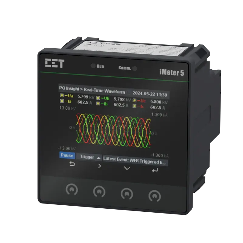
iMeter 5 Advanced Power Quality Monitor

iMeter 6 Advanced Power Quality Monitor
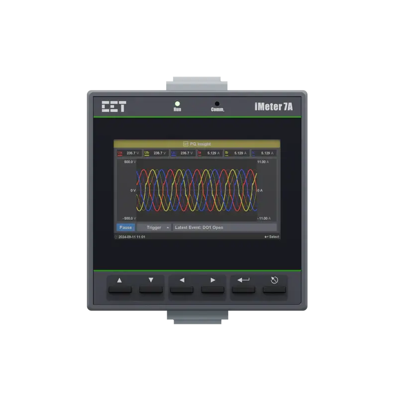
iMeter 7A Advanced Power Quality Monitor
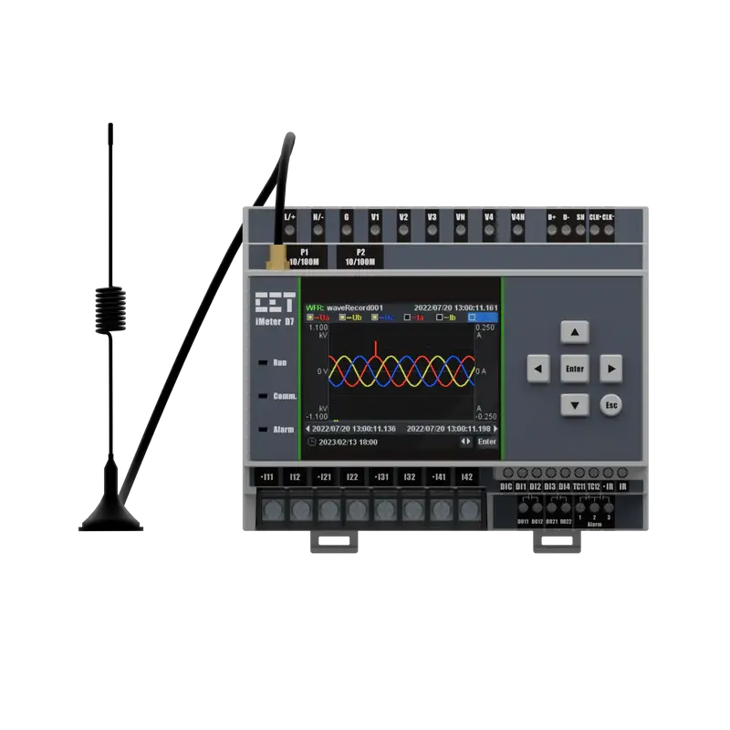
iMeter D7 Advanced Power Quality Monitor
Specification
Technical Specification
Voltage Inputs(V1,V2,V3,VN) | |
|---|---|
| Standard Un | 400VLN/690VLL+20% |
| Range | 4V to 120%Un |
| PT Ratio Primary Secondary | 1 to 1,000,000 1 to 1,500 |
| Overload | 1.2xUn continuous, 2xUn for 10 s |
| Burden | <0.5VA@240V |
| Measurement Category | CAT III 600ULL |
| Frequency | 42-69Hz |
Current Inputs(I11,I12,I21,I22,I31,I32,I41,I42) | |
| Standard In | 5A(Optional 1A) |
| Range | 0.1% to 200%In |
| Starting Current | 0.1%In |
| Overload | 2xIn continuous, 20xIn for 1 s |
| Measurement Category | CAT III up to 600ULL |
| Burden | <0.15VA per phase@5A |
Optional I4 Input(I41,I42) | |
| In | 5A(5A/1A Auto-Scale) |
| Range | 0.1% to 200% In |
| Starting Current | 0.1% In |
Power Supply(L+,N-) | |
| Standard | 95-250VAC/DC,±10%,47-440Hz |
| Optional | 20-60VDC |
| Burden | <2W |
| Overvoltage Category | CAT III up to 300VLN |
Digital Inputs(DI1,DI2,DI3,DI4,DIC) | |
| Type | Dry contact,24VDC internally wetted |
| Sampling | 1000Hz |
| Hysteresis | 1ms minimum |
Digital Outputs(DO11,DO12,DO21,DO22) | |
| Type | Form A Mechanical Relay |
| Loading | 5A@250VAC or 30VDC |
| Load Type | Resistive |
Pulse Outputs(E1+,E1-,E2+,E2-) | |
| Type | Form A Solid State Relay |
| Isolation | Optical |
| Load Type | Resistive |
| Output | Optocoupler output as ON-OFF |
| Max.Load Voltage | 50VDC |
| Max.Forward Current | 50mA |
Installation Torque | |
| Current Inputs | 12 Ib-in(1.3N.m) |
| Power Supply,Voltage Inputs,RS-485 and I/O | 5 Ib-in(0.5N.m) |
Environmental Conditions | |
| Operating Temp. | -25 °C to + 70°C |
| Storage Temp. | -40 °C to + 85°C |
| Humidity | 5% to 95% non-condensing |
| Atmospheric Pressure | 70 kPa to 106 kPa |
| Altitude | <2000m |
| Location/Mounting | For indoor use only |
Mechanical Characteristics | |
| Panel Cutout | 92x92mm(3.62”x3.62”) |
| Unit Dimensions | 96x96x88mm |
| IP Rating | IP65 |
Communications | |
| Protocol | Modbus RTU, BACnet MS/TP, Metasys N2 and DNP3.0 |
| RS-485 Port | 1+(1 Opt.) |
Features Summary | |
| Display (Backlit) | Dot-Matrix LCD (Backlit) |
| Type of Measurement | ULN per Phase &Avg. ULL per Phase&Avg. Current per Phase &Avg. Neutral Current (Meas./Calc.) Frequency kW per Phase & Total kvar per Phase & Total kVA per Phase& Total PF per Phase& Total kWh lmport/Export kvarh Import/Export kVAh Total |
| Power Quality | THD Voltage & Current TOHD Voltage & Current TEHD Voltage & Current 2nd-31st Harmonics K-Factor Voltage/Current Unbalance |
| Battery-backed Real-time Clock | √ |
| Demands | Present , Predicted Demands and Max.Demands for This Month & Last Month |
| Multi-Tariff TOU capability | Two TOU schedules, each providing: 12 Seasons 90 Holidays 20 Daily Profiles, each with 12 Periods in 15-minute interval 8 Tariffs |
| Diagnostics | √ |
| Setpoints | 9 Setpoints |
Logs | |
| Max./Min.Log | This month & Last Month |
| Freeze Logs(Optional) | 60 Daily Freeze Logs, 36 Monthly Freeze Logs |
| Data Recorder(Optional) | 5 Data Recorders Max. Recording Depth @ 10000 records |
| SOE Log | 100 entries |
| On-board Log Memory | (4MB Opt.) |
Accuracy
| Parameters | Accuracy | Resolution |
|---|---|---|
| Voltage | ±0.2% | 0.001V |
| Current | ±0.2% | 0.001A |
| I4(measurement) | ±0.2% | 0.001A |
| P,Q,S | ±0.5% | 0.001kx |
| kWh,kVAh | IEC 62053-22 Class 0.5S ANSI C12.20 Class 0.2 EN 50470-1/3:2006 Class C | 0.1kXh |
| kvarh | IEC 62053-24 Class 0.5S IEC 62053-23 Class 2 | 0.1kvarh |
| PF | ±0.5% | 0.001 |
| Frequency | ±0.02Hz | 0.01Hz |
| THD | IEC 61000-4-7 Class B | 0.001% |
| K-Factor | IEC 61000-4-7 Class B | 0.001 |
| Phase Angle | ±1° | 0.1° |
Standards of Compliance
Safety Requirements | |
|---|---|
| CE LVD 2014/35/EU | EN 61010-1: 2010 EN 61010-2-030: 2010 |
| Electrical Safety in Low Voltage Distribution Systems up to 1000Vac and 1500Vdc | IEC 61557-12:2018(PMD) |
| Insulation AC Voltage: 2kV@1 minute Insulation Resistance: >100MΩ Impulse Voltage: 6kV,1.2/50µs | IEC 62052-31:2015 |
Electromagnetic Compatibility CE EMC Directive 2014/30/EU(EN 61326:2013) | |
Immunity Tests | |
| Electrostatic Discharge | EN 61000-4-2:2009 |
| Radiated Fields | EN 61000-4-3:2006+A1:2008+A2:2010 |
| Fast Transients | EN 61000-4-4:2012 |
| Surges | EN 61000-4-5:2014+A1:2017 |
| Conducted Disturbances | EN 61000-4-6:2014 |
| Magnetic Fields | EN 61000-4-8:2010 |
| Voltage Dips and Interruptions | EN 61000-4-11:2004+A1:2017 |
| Ring Waves | EN 61000-4-12:2017 |
Emission Tests | |
| Limits and Methods of Measurement of Electromagnetic Disturbance Characteristics of Industrial,Scientific and Medical(ISM) Radio-Frequency Equipment | EN 55011:2016 |
| Limits and Methods of measurement of Radio Disturbance Characteristics of Information Technology Equipment | EN 55032:2015 |
| Limits for Harmonic Current Emissions for Equipment with Rated Current≤16A | EN 61000-3-2:2014 |
| Limitation of Voltage Fluctuations and Flicker in Low-Voltage Supply Systems for Equipment with Rated Current≤16A | EN 61000-3-3:2013 |
| Emission Standard for Residential, Commercial and Light-Industrial Environments | EN 61000-6-4:2007+A1:2011 |
RED (Radio Equipment Directive) | |
| Assessment of Electronic and Electrical Equipment Related to Human Exposure Restrictions for Electromagnetic Fields (0Hz - 300 GHz) | EN/IEC 62311: 2020 |
| Short Range Devices (SRD) Operating in the Frequency Range 25 MHz to 1000MHz | ETSI EN 300 220-1V3.1.1: 2017 ETSI EN 300 220-2 V3.1.1: 2017 |
| Audio/Video, Information and Communication Technology Equipment -Part 1: Safety Requirements | IEC 62368-1: 2018 |
Mechanical Tests | |
| Spring Hammer Test | IEC 62052-11:2003 |
| Vibration Test | IEC 62052-11:2003 |
| Shock Test | IEC 62052-11:2003 |
Wiring Mode
Wiring Mode | |
|---|---|
| 3P4W | 3-Phase 4-Wire Wye Direct Connection with 3CTs 3-Phase 4-Wire Wye Direct Connection with 4CTs 3-Phase 4-Wire Wye with 3PTs and 3CTs 3-Phase 4-Wire Wye with 3PTs and 4CTs |
| 3P3W | 3-Phase 3-Wire Direct Delta Connection With 3CTs 3-Phase 3-Wire Direct Delta Connection with 2CTs 3-Phase 3-Wire Delta with 2PTs and 3CTs 3-Phase 3-Wire Delta with 2PTs and 2CTs |
| 1P3W | 1-Phase 3-Wire Direct Connection with 2CTs |
| 1P2W L-N | 1-Phase 2-Wire, Uln Direct Connection with 1CT |
| 1P2W L-L | 1-Phase 2-Wire, Ull Direct Connection with 1CT |