Main Documents
Description
PMC-592 Multi Circuit Power Monitor
Device Introduction
- The PMC-592 MCPM is the ultimate solution for PDU, LVDB and Load Center applications that require multi-circuit monitoring. Housed in a compact metal enclosure, the PMC-592 is perfectly suited for applications that require high density metering.
- The PMC-592 features quality construction with multifunction and High-Accuracy measurements, two Mains Inputs, up to 84 Branch Circuit Inputs and an optional 7” Touch-Screen HMI. The PMC-592 comes standard with two Digital Inputs for status monitoring, two Digital Outputs for control or alarming as well as two RTD Inputs for temperature measurements. The standard SOE Log records all setup changes, Setpoint alarms and DI/DO operations in 1ms resolution. With Ethernet and dual RS-485 as standard feature supporting Modbus RTU/TCP, HTTP, SMTP as well as SNMP, the PMC-592 becomes a vital component of an intelligent, multi-circuit monitoring solution
Product Highlight
- Multi-Circuit Power Monitor
- IEC 62053-22 Class 0.5S for Mains, IEC62053-21 Class 1 for Branches
- 260.5x154x55.5mm
- LED Indicators, Optional Touch Screen HMI
- 2 Mains Inputs each with 3xV & 4xI, 84 Branch Circuits with CT-Strip Accessories
- Harmonics, Demands, Waveform Log, Dip/Swell Log and Event Log
- 1GB On-board Memory
- Modbus RTU/TCP, SNMP, HTTP, SMTP, SNTP
- 1xEthernet, 2xRS-485
- 2xDI, 2xDO, 1xRTD
Typical Application
- Data Center PDUs
- Clean room LVDB (Low-Voltage Distribution Board)
- Load Center Monitoring
- Ring Main Unit Metering
- Motor Control Center metering
- Commercial & Residential LV High-Density Multi-Circuit monitoring
Related Products
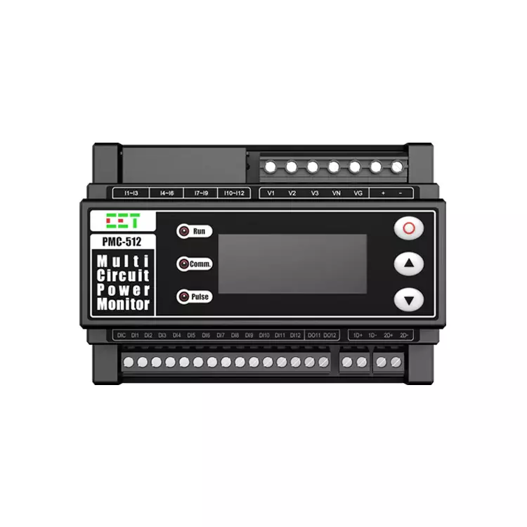
PMC-512-A AC Multi-Circuit Power Monitor
Specification
Technical Specification
Voltage Inputs(V1,V2,V3,VN) | |
| Standard Un | 240VLN/415VLL |
| Range | 10V to 1.2Un |
| Start Voltage | 10V |
| Overload | 1.2xUn continuous, 2xUn for 10s |
| Burden | <0.05VA/phase |
| Frequency | 45-65Hz |
| Voltage Inputs(VN,VG) | |
| Range | 0~5V |
Current Inputs(I11,I12,I21,I22,I31,I32) | |
| In Primary | 5A/100A/200A/250A/400A/800A |
| In Secondary | 1.667mA for 5A 40mA for 100A/200A/250A/400A/800 |
| Range | 0.4% to 100% In Primary |
| Starting Current | 0.004 In Primary |
| Solid Core CT Range 100A Molded Case CT (3-Ø) 250A Solid Core CT (1-Ø) 400A Solid Core CT (1-Ø) 800A Solid Core CT (1-Ø | 0.4~100A 1~250A 1.6~400A 3.2~800A |
| Split Core CT Range 5A SCCT (1-phase) 100ASCCT(1-phase) 200ASCCT(1-phase) 400ASCCT(1-phase) 800ASCCT(1-phase) | 0.02~5A 0.4~100A 0.8~200A 1.4~400A 3.2~800A |
Burden | <0.3 VA per phase @In |
| Overload | 1.0xIn Primary (continuous) |
Power Supply(L+,N-) | |
Standard | 95-250VAC/VDC ± 10%, 47-440 Hz |
Optional | 20-60VDC |
| Burden | <2W |
Digital Inputs | |
Type | 48VDC External Excitation |
Digital Outputs | |
Type | Form A Mechanical Relay |
Loading | 5A@250VAC or 30VDC |
| Analog Input | |
| Type | 0-20/4-20mA |
| Overload | 24mA maximum |
Installation Torque | |
Power Supply/Voltage Input | 0.8N.m |
| AI /RS485 | 0.2N.m |
| DO /DI | 0.4N.m |
Environmental Conditions | |
Operating Temp. | -25 °C to + 70°C |
Storage Temp. | -40 °C to + 85°C |
Humidity | 5% to 95% non-condensing |
Atmospheric Pressure | 70 kPa to 106 kPa |
Altitude | ≤3000m |
Mechanical Characteristics | |
Unit Dimensions | 126x90x65mm |
IP Rating | IP50 |
Communications | |
Protocol | Modbus RTU, |
RS-485 Port | 2 |
Features Summary | |
Display (Backlit) | Dot-Matrix LCD (Backlit) |
Type of Measurement | ULN per Phase &Avg. ULL per Phase&Avg. Current per Phase &Avg. Neutral Current (Meas./Calc.) Frequency kW per Phase & Total kvar per Phase & Total kVA per Phase& Total PF per Phase& Total kWh lmport/Export kvarh Import/Export kVAh Total |
Power Quality | THD Voltage & Current TOHD Voltage & Current TEHD Voltage & Current 2nd-31st Harmonics K-Factor Voltage/Current Unbalance |
Battery-backed Real-time Clock | √ |
Demands | Present Demands and Max.Demands for This Month & Last Month |
Alarm Setpoints | √ |
Logs | |
Max./Min.Log | 24 Months |
Freeze Logs(Optional) | 1000 Daily Freeze Logs, 24 Monthly Freeze Logs |
Data Recorder(Optional) | 1 Data Recorder Max. Recording Depth @ 5000 record s |
SOE Log | 512 entries |
On-board Log Memory | 4MB |
Accuracy
| Parameters | Accuracy | Resolution |
|---|---|---|
| Voltage | ±0.5% | 0.01V |
| Current | ±0.5% | 0.001A |
| Phase Angle | ±1° | 0.1° |
| kW,kvar,kVA | ±1.0% | 0.001kx |
| kWh | IEC 62053-21:2003 Class 1 | 0.01kXh |
| kvarh | IEC 62053-24:2014 Class 1 | 0.01kvarh |
| AI | ±1.0% | - |
| PF | ±0.5% | 0.001 |
| Frequency | ±0.02Hz | 0.01Hz |
| THD | IEC 61000-4-7 Class B | 0.1% |
| Voltage Unbalance | ±0.2% | 0.01% |
| Current Unbalance | ±1.0% | 0.01% |
Standards of Compliance
Safety Requirements | |
|---|---|
| CE LVD 2014/35/EU | EN 61010-1: 2010 EN 61010-2-030: 2010 |
| Electrical Safety in Low Voltage Distribution Systems up to 1000Vac and 1500Vdc | IEC 61557-12:2008 |
| Insulation AC Voltage: 2kV@1 minute Insulation Resistance: >100MΩ Impulse Voltage: 6kV,1.2/50µs | IEC 60255-5-2000 |
Electromagnetic Compatibility CE EMC Directive 2014/30/EU(EN 61326:2013) | |
Immunity Tests | |
| Electrostatic Discharge | EN 61000-4-2:2009 |
| Radiated Fields | EN 61000-4-3:2006+A1:2008+A2:2010 |
| Fast Transients | EN 61000-4-4:2012 |
| Surges | EN 61000-4-5:2006 |
| Conducted Disturbances | EN 61000-4-6:2009 |
| Magnetic Fields | EN 61000-4-8:2010 |
| Oscillatory Waves | EN 61000-4-12:2006 |
Emission Tests | |
| Limits and Methods of Measurement of Electromagnetic Disturbance Characteristics of Industrial,Scientific and Medical(ISM) Radio-Frequency Equipment | EN 55011:2009 + A1:2010 (CISPR11) |
| Limits and methods of measurement of radio disturbance characteristics of information technology equipment | EN 55022:2010 + AC:2011 (CISPR22) |
| Limits for Harmonic Current Emissions for Equipment with Rated Current≤16A | EN 61000-3-2:2014 |
| Limitation of Voltage Fluctuations and Flicker in Low-Voltage Supply Systems for Equipment with Rated Current≤16A | EN 61000-3-3:2013 |
| Emission Standard for Residential, Commercial and Light-Industrial Environments | EN 61000-6-4:2007+A1:2011 |
| Electromagnetic Emission Tests for Measuring Relays and Protection Equipment | EN 61000-4-12:2006 |
Mechanical Tests | |
| Vibration Test Response Endurance | IEC 62052-11:2003 Level I IEC 62052-11:2003 Level I |
| Shock Test Response Endurance | IEC 62052-11:2003 Level I IEC 62052-11:2003 Level I |
| Bump Test | IEC 62052-11:2003 Level I |
Wiring Mode
Wiring Mode | |
|---|---|
| 3P4W | 3P4W without PTs & with VG 3P4W without PTs & VG 3P4W with VG and PTs |
| 3P3W | 3-Phase 3-Wire without PTs 3-Phase 3-Wire with PTs |
| 1P2W | 1-Phase 2-Wire Wiring with VG 1-Phase 2-Wire Wiring without VG |