Main Documents
Description
PMC-550J Low-Voltage Motor Control and Protection Relay
Device Introduction
- PMC-550J is CET’s latest offer to integrate motor Protection, Control and Monitoring solution in one metal box. It is an ideal choice for intelligent MCC (Motor Control Centre) and is widely used in manufacturing industries such as Petrochemical, Coal, Paper, Steel and Metallurgy industry. PMC-550J realizes different protection and control applications for LV motors via its high precision circuitry, advanced protection & control schemes, configurable DI and DO functions as well as its network communication features to ensure operation reliability.
Product Highlight
- Low-voltage Motor Protection and Control Device
- High Accuracy Power/Energy Measurements
- Device Size:126x76x90.3mm, Aperture Size:121x71mm
- Backlit B&W Dot-Matrix LCD Display
- Enhanced Power Supply with 30s Ride-through Capability for Voltage Dips
- PQ and Harmonic Monitoring, Event Log
- Modbus RTU
- 1xRS-485, 1xType-C USB
- 8xDI, 5xDO, Optional 1xAO, 1xProfibus-DP
| Start Wiring | ||
| Direct-On-Line Start | PowerLogic | |
| Reduce-voltage | Star-Delta Start | |
| Auto-transformer Start | ||
| Resistance Start | ||
Forward-reverse Start | ||
| Two-speed Start | ||
| Variable Frequency Driver (VFD) Start | ||
| Large Motor Start | ||
Related Products
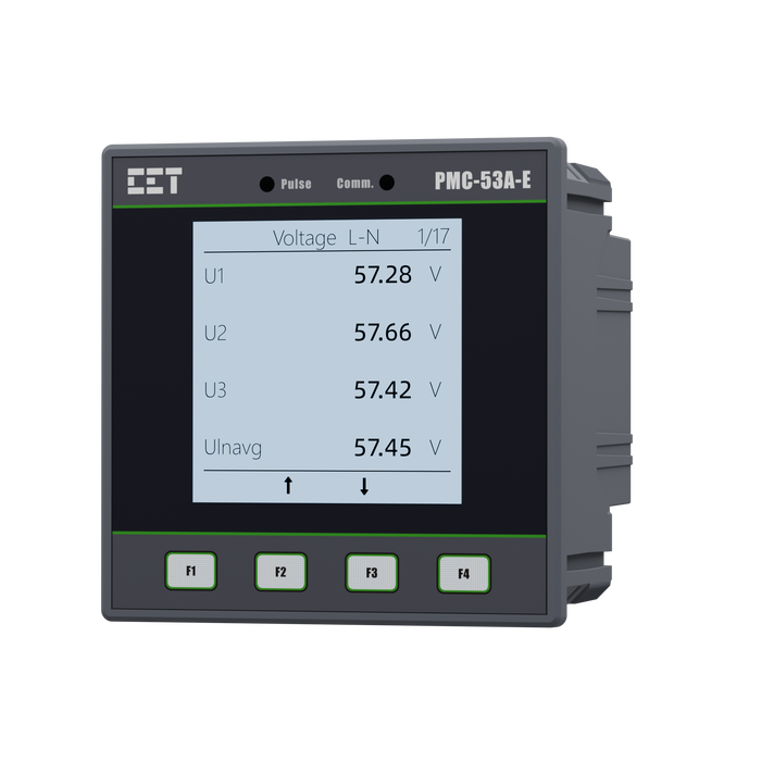
PMC-53A-E Ethernet Multifunction Meter
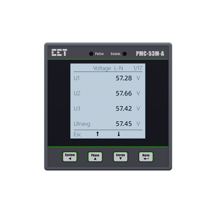
PMC-53M-A Digital Multifunction Meter
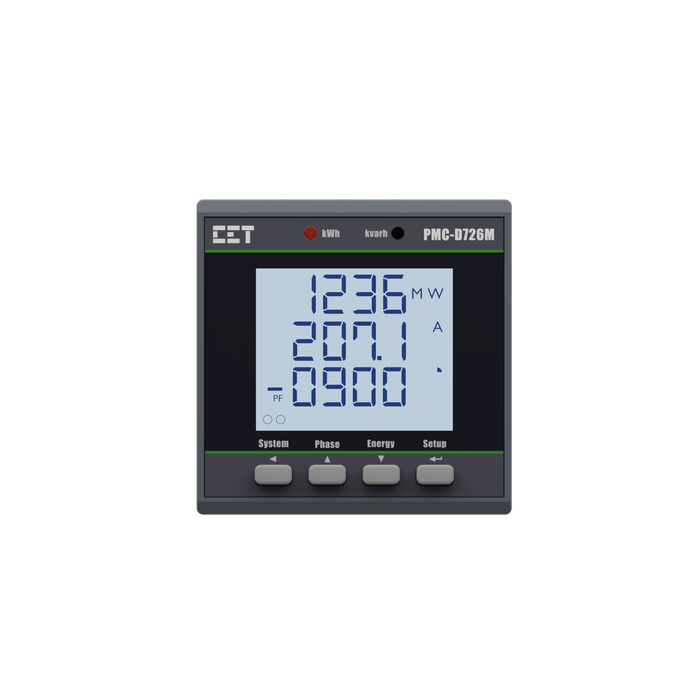
PMC-D726M Digital Multifunction Meter
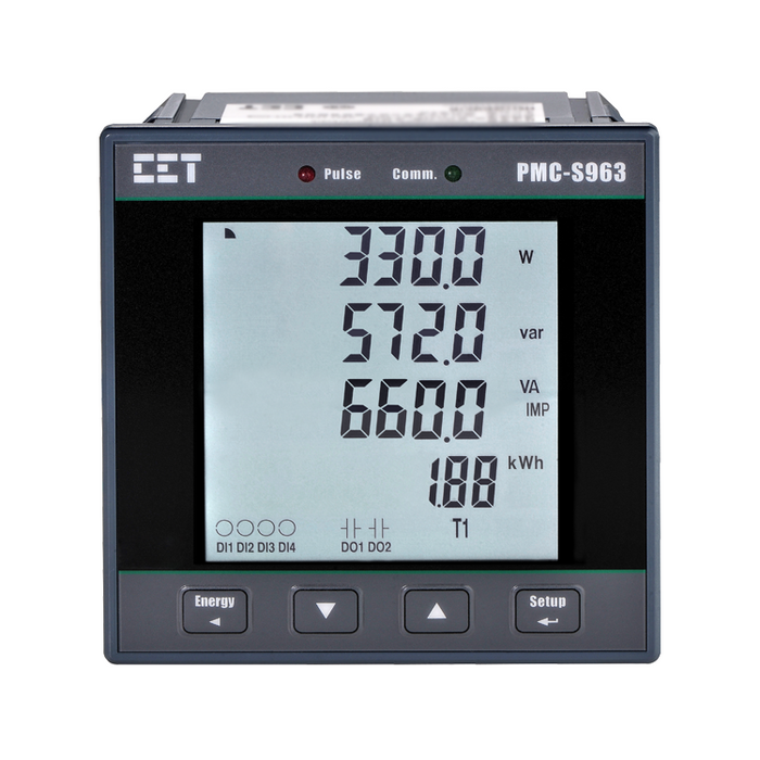
PMC-S963-C Intelligent Multifunction Meter
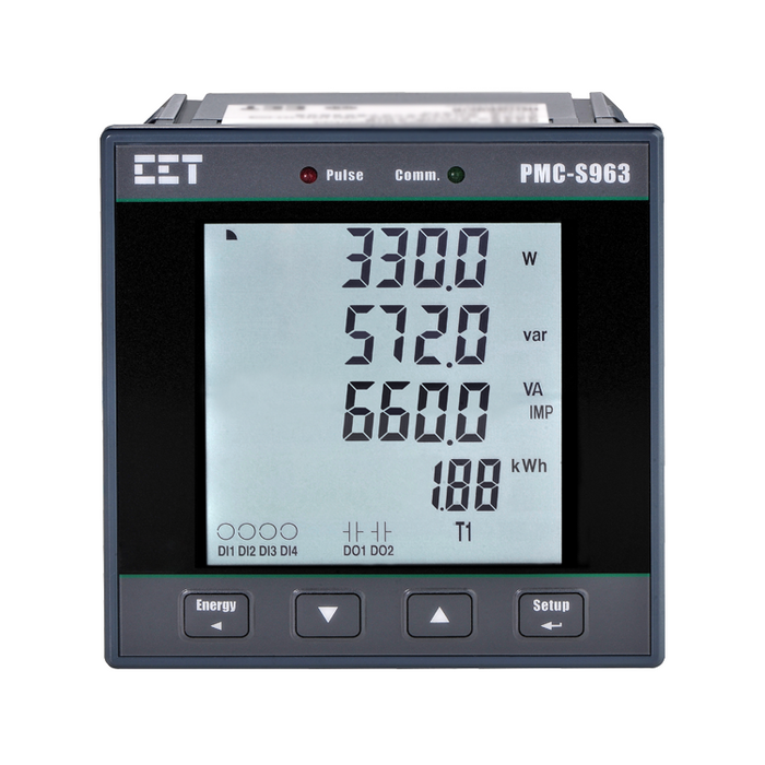
PMC-S963-E Intelligent Multifunction Meter
Related Solutions
Specification
Technical Specification
Voltage Inputs(VA,VB,VC) | ||
| Standard(Vn) | 400VLN/690VLL | |
| Range | 10V to 828V for 690VLL | |
| Overload | 1.2xVn continuous, 1.4xVn for 10s | |
| Burden | <0.75VA per phase | |
| Frequency | 50Hz/60Hz | |
| Current Inputs | ||
Plug-in Current Sensor PMC-MTAs (IA,IB,IC,IN) | ||
| Ie | 1A/5A/25A/100A/300A/400A/800A | |
| Range | 5% to 120% Ie | |
| Overload | 10xIe for 10s | |
| Optional Residual Current Sensor PMC-MIR (IR1,IR2) | ||
| Primary (In) | 1A | |
| Secondary | 1V | |
| Imax | 2In continually | |
| Optional Zero Sequence Current Sensor PMC-MIN (I41,I42) | ||
| Primary (In) | 1A/5A | |
| Secondary | 1V | |
| Range | 5% to 120%In | |
| Imax | 10In | |
Power Supply (L/+,N/-) | ||
Standard | 95-250VAC/DC | |
Optional | Enhanced power supply(ride-through capability) | |
| Burden | <5W | |
Digital Inputs (DIC,DI1,DI2,DI3,DI4,DI5,DI6,DI7,DI8) | ||
Standard | Dry contact, 24VDC internally wetted | |
Debounce Time | 20~9999 ms programmable | |
Relay Outputs (DO11,DO12,DO21,DO22,DO31,DO32,DO41,DO42,DO51,DO52) | ||
Type | DO1 Form B (NC),DO2 FormA (NO) or Form B (NC), DO3 to DO5 Form A (NO) | |
DO1toDO4 | DO5 | |
| Contact Rating | 250 VAC/24 VDC, 8A | 250 VAC/30 VDC,5A |
| Max. Switching Voltage | 400 VAC/30 VDC | 277 VAC/30 VDC |
| Max. Carrying Current | 10A | 5A |
| Max. Switching Power | 2000VA/192W | 1250VA/150W |
| Operate Time | <10ms | <10ms |
| Release Time | <5ms | <10ms |
| Service Life | >20,000,000 cycles (Mechanical) | >5,000,000 cycles (Mechanical) |
| >100,000 cycles (Electrical at rated load) | >100,000 cycles (Electrical at rated load) | |
| Internal Clearance/Creepage Distance | >8mm(Safety Insulation up to 250VAC) | >6mm (Safety Insulation up to 250VAC |
| (EN 61810-1,Pollution Degree 3) | (EN 61810-1, Pollution Degree 2) | |
Optional Analog Output (AO+,AO-) | ||
Load | 750 ohms | |
| Range | 4 to 20mA | |
Terminals Max.Torque | ||
Power Supply, DI, DO, RS-485 | 3.5 in.lb (0.4 Nm) | |
AO | 1.7 in.lb (0.2 Nm) | |
Environmental Conditions | ||
Operating Temp. | -25°C to 55°C | |
Humidity | 5% to 95% non-condensing | |
Atmospheric Pressure | 70 kPa to 106 kPa | |
Mechanical Characteristics | ||
Panel Cutout | 121x71mM | |
Unit Dimensions | 126x76x91mM | |
IP Rating | 40 | |
Communications | ||
Protocol | Modbus, ProfibuS | |
RS-485 Port | 1 | |
| Type-C USB Port | 1 | |
| Optional PROFIBUS-DP Port | 1 | |
Measurements | ||
ULL per Phase | √ | |
Current per Phase | √ | |
Neutral Current(Meas./Calc.) | √ | |
Frequency | √ | |
Residual Current | √ | |
Total active power | √ | |
Total reactive power | √ | |
Total power factor | √ | |
| kWh Import/Export | √ | |
| kvarh Import/Export | √ | |
| Power Quality | ||
| THD Voltage&Current | √ | |
| TOHD Voltage&Current | √ | |
| TEHD Voltage&Current | √ | |
| Individual Harmonics | 2nd-31st | |
| Voltage Phase Angle | √ | |
| Current Phase Angle | √ | |
| Current Unbalance | √ | |
| Protection Functions | ||
| Jam Protection | √ | |
| Start Overtime | √ | |
| Thermal Overload | √ | |
| Overload | √ | |
| Process Interlock | √ | |
| tE Inverse Time | √ | |
| Short-Circuit | √ | |
| Ground Fault | √ | |
| Residual Current | √ | |
| Loss of Phase | √ | |
| Over-Voltage | √ | |
| Under-Voltage | √ | |
| Imbalance | √ | |
| Phase Reversal | √ | |
| Negative Phase Seq. | √ | |
| Current Transducer(MTA) Failure | √ | |
| Contactor Failure | √ | |
| Block When Start | √ | |
Motor Control & Start | ||
Under-Voltage Restart | √ | |
Auto-Start Function | √ | |
Local/Remote Control | √ | |
Direct-On-Line | √ | |
Forward-Reverse Start | √ | |
| Two-Speed Start | √ | |
| Star-Delta Starter | √ | |
| Motor ON/OFF Sequence | √ | |
Accuracy
| Parameters | Accuracy | Resolution |
|---|---|---|
| Voltage(U) | ±0.5% | 0.001V |
| IN | ±0.5% | 0.001A |
| Ir | 20mA to 1200mA: ±1.0% | 1mA |
| 1200mA to 5000mA: ±3.0% | ||
| kW,kvar,kVA | ±1.0% | 0.001kx |
| kWh | ±1.0% | 0.01kWh |
| kvar | +2.0% | 0.01kvarh |
| PF | ±1.0% | 0.001 |
| Frequency | ±0.02Hz | 0.001Hz |
| Analog Output | ±2.0% | -- |
| Harmonics | IEC 61000-4-7 Class II | 0.01% |
Standards of Compliance
Safety Requirements | |
|---|---|
| Insulation AC Voltage: 2kV @ 1 minute Insulation Resistance: >100MΩ Impulse Voltage: 5kV,1.2/50µs | IEC 60255-5:2000 |
EM Compatibility | |
Immunity Tests | |
| Electrostatic Discharge | IEC 61000-4-2:2009 Level IV |
| Radiated Fields | IEC 61000-4-3:2006 + A1:2008 + A2:2010 Level III |
| Fast Transients | IEC 61000-4-4:2012 Level IV |
| Surges | IEC 61000-4-5:2014+A1:2017 Level IV |
| Conducted Disturbances | IIEC 61000-4-6:2014 Level III |
| Power Frequency Magnetic Fields | IEC 61000-4-8:2010 Level V |
| Pulsed Magnetic Fields | IEC 61000-4-9:2016 Level V |
| Damped Oscillatory Magnetic Fields | IEC 61000-4-10:2016 Level V |
| Voltage Dips and Interruptions | IEC 61000-4-11:2004+A1:2017 Level III |
| Ripple on DC Input Power Port | IEC 61000-4-17:2009 Level IV |
| Damped Oscillatory Wave | IEC 61000-4-18:2019 Level III |
| Power Frequency Immunity on Binary Inputs | IEC 60255-26:2013 Class A |
| Gradual Shut Down / Start-up Tests | IEC 60255-26:2013 |
Emission Tests | |
| Radiated Emission | IEC 60255-26:2013 |
| Conducted Emission | IEC 60255-26:2013 |
Mechanical Tests | |
| Vibration Test(Response/Endurance) | IEC 60255-21-1:1988 Level I |
Shock Test(Response/Endurance) | IEC 60255-21-2 Level II |
| Bump Test(Response Endurance) | IEC 60255-21-2 Level I |